Home

Replacing the LCD backlight in Philips PM 3055, PM3365 and similar oscilloscopes


Please Note : This procedure requires some skill at soldering and at least a minimum amount of electronics knowledge.

!!!!Safety Concerns!!!!!

Make sure the Oscilloscope is OFF and DISCONNECTED from the mains!
Use antistatic techniques, the circuits inside can be damaged by STATIC.
There are potentially dangerous voltages inside this instrument, however in the area concerned there is only low voltage, but once again...POWER OFF and DISCONNECT FROM THE MAINS and remove any inputs to the oscilloscope!!

NO LIABILITY ACCEPTED FOR ANY DAMAGE TO YOU OR YOUR OSCILLOSCOPE FROM FOLLOWING THIS PROCEDURE.
Your calibration warranty will probably be void after opening the case.

The photo's are from a digital PM3365, if you are doing this on the analog versions eg PM3055, it is much simpler in that you do not need to remove the digital unit,  access to the LCD panel screws is directly after removing the top cover. When following this procedure DO NOT FORCE ANYTHING! If it won'tcome apart or fit back together easily find out why! The LCD is easily damaged both by force or static, be gentle! Dress the cables properly and don't forget to put the earth tags back! If you leave them loose they will short something ! Use a small 25-30W fine tip pencil type soldering iron, preferably temperature controlled eg Weller or if you must use Radioshack get the small grounded type of soldering iron. Mains irons with no ground lead will possibly damage the circuitry.

After removing the top cover (one screw at rear of case), remove this screw, usually the only one holding the board down

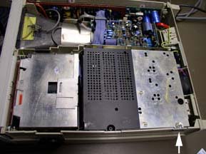
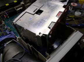
Remove 2 Earth tags (remember to replace them!)

Lift the shielded board assy up and clip it to the side, the cables are tight but it will go.

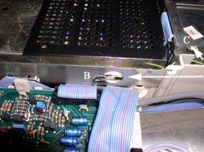
Lift the digital unit straight up & remove 2 cables

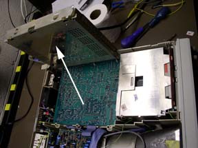
Now you can move the digital unit aside just enough to see the 2 screws holding the front panel

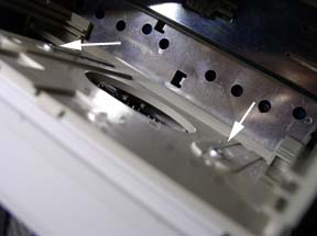
Remove the 2 long mounting screws

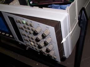
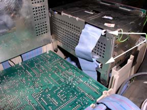
The display panel is now loose, ease it out gently
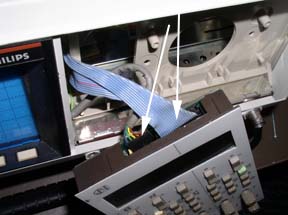
Remove the 2 cables

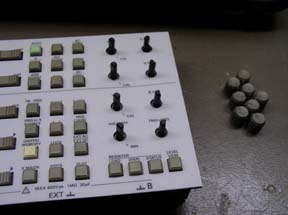
Pull all the knobs off

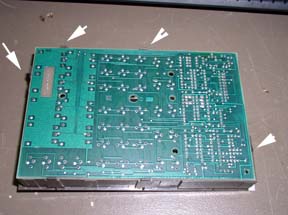
The circuit board is held in place by a number of clips. Ease them aside to pop the board out. Be very pleased with yourself if you do this without breaking the clips!

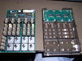
Now you can see the LCD board

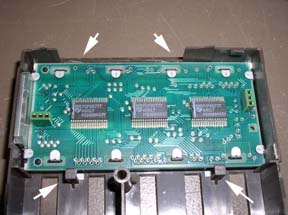
Again , ease the clips aside to pop the board out.. They almost always break .

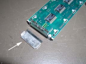
Dont lose the reflector

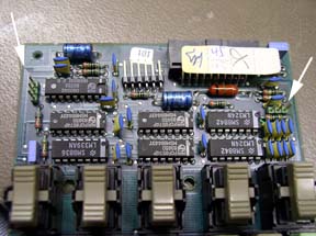
Now you need to unsolder the 2 lamp wires

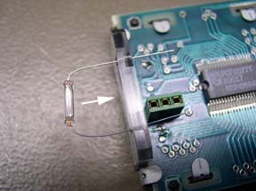
Insert the new lamp through the holes  and push it into the slot

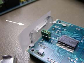
A bit of tape holds it flush for soldering, cut the wires to length.

Solder the wires in place, watch out for solder splashes! Clean and inspect after soldering

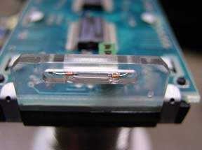
Remove the tape, the lamp should be flush with the surface, put the reflector in place.

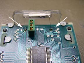
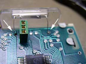
The LCD board has to connect to the 2 multi pin connectors

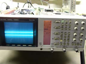
Go backwards through this procedure to reassemble the 'scope and you should have a nice backlit display again! Don't worry if you broke all or most of the board clips, the assembly holds together ok when its screwed back in place

Top      Home